

Blow-Fill-Cap Combiblock
The combiblock combines a blow molder, filler and capper into a single unit: the bottle moves from mold to fill valve in seconds, with no air conveyor or buffers.
- Product
- Water, carbonated beverages, juices, tea
- Container
- PET, 0.25–2.0 L
- Output
- 5,500–30,000 bph depending on volume
- Model range
- KM-CGX06-18-06 … KM-CGX18-60-20
- Blow cavities
- 6–18
- Fill valves
- 18–60
- Capping heads
- 6–20
- Space savings
- 25–40 % versus a separate-unit layout
Line parameters
About the solution
A conventional layout requires an air conveyor, a buffer accumulator and synchronization of three separate machines. The combiblock removes these links: the bottle is transferred directly by a mechanical star wheel, cutting the line's footprint by 25–40 % and reducing the risk of container contamination.
The KM-CGX06-18-06 … KM-CGX18-60-20 model range covers 5,500 to 30,000 bph depending on container volume. Fewer stations mean fewer failure points, and lower electricity and compressed-air consumption per bottle.
Built into the design
No conveyor between stations
Bottle transfer by mechanical star wheels: a short, fully enclosed path from blowing to capping.
Smaller floor plan
Removing the air conveyor and accumulator frees up roughly a quarter of the line's footprint.
Single control system
One PLC and one HMI for three operations — simpler operation, fewer synchronization issues.
Energy savings
Fewer drives and less compressed air per bottle compared with a separate-unit layout.
Line composition along the product flow
8 positions along the product flow. Every unit opens in the catalog: series, specifications, scope of supply and a quote request.
- 1
1. Preform feeding and orientation
Hopper, elevator, orientation and feeding of preforms into the heating oven.
Blow-fill-cap combiblock →
- 2
2. Infrared heating oven
Zoned preform heating with independent control along the profile height.
Blow-fill-cap combiblock →
- 3
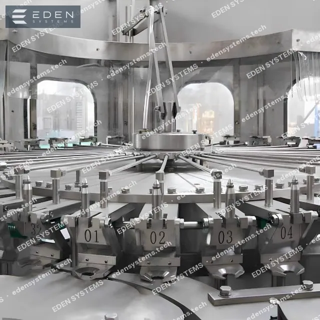
3. Blow-molding rotor
Stretch-rod drawing and two-stage blowing up to 40 bar, mold cooling.
Blow-fill-cap combiblock →
- 4
4. Transfer star wheel
Direct transfer of the hot bottle into the filling rotor with no conveyor.
Blow-fill-cap combiblock →
- 5
5. Filling rotor
Gravity or isobaric filling depending on the product.
Blow-fill-cap combiblock →
- 6
6. Capping rotor
Cap application with torque control and rejection of defects.
Capping equipment →
- 7
7. Inspection and date coding
Fill-level and cap-presence checks and batch date coding.
Marking and quality inspection →
- 8
8. Labeling and packing
Roll-fed labeling, shrink packing and palletizing.
Labelling equipment →
Line model selection
Selecting a combiblock for CSD at 30,000 btl/h
Model range for carbonated beverages, 0.5 L container. Full blowing, filling, and capping specifications are in the "Combiblock" section.
| Model | Blow cavities | Filling valves | Capping heads | Output (0.5 L) |
|---|---|---|---|---|
| EDS-DCX 14-60-15 | 14 | 60 | 15 | 24,000 btl/h |
| EDS-DCX 16-80-15 | 16 | 80 | 15 | 27,000 btl/h |
| EDS-DCX 18-90-18 | 18 | 90 | 18 | 30,000 btl/h |
| EDS-DCX 20-108-20 | 20 | 108 | 20 | 36,000 btl/h |
For 30,000 btl/h the base model is EDS-DCX 18-90-18. Adjacent models are shown for headroom and growth potential assessment.
Line composition and floor space
Approximate values for a "combiblock + auxiliary equipment" package at 30,000 btl/h.
| Parameter | Value |
|---|---|
| Installed line power | ≈170 kW |
| Filling area floor space | 800–1,000 m² |
| Operators per shift | 5–6 |
| Floor space savings vs. separate scheme | 25–40% |
Floor space and power are refined after agreeing on the plant layout and auxiliary system scope.
Line process flow
At 30,000 btl/h the combiblock handles blowing, filling, and capping in a single unit — the line is shorter and needs no air conveyor. The "head" and "tail" of the CSD line include product carbonation and bottle warming before labeling; see the "Combiblock" section for the technology of the blow-fill-cap unit itself.
What the combiblock brings to a CSD line
- One unit instead of three separate machines — a shorter bottle path, fewer transfer points, and less container breakage
- 25–40% floor space savings in the filling area from eliminating the air conveyor and buffer
- A single PLC for blowing, filling, and capping — a 30,000 btl/h line is run by 5–6 operators
- Isobaric filling of CO₂ beverages with no desynchronization between blowing and filling
- Camera inspection of the preform neck and bottle backlight — defects removed before the product is added
- Fast bottle format changeover without stopping to replace the air path
Full layout for the EDS-DCX 18-90-18 rate: from preform and syrup to the finished pallet.
- 1Preform feeding and orientation
- 2Mixer-carbonator
- 3Blow-fill-cap combiblock (isobaric)
- 4Cap feeding and rinsing
- 5Bottle backlight inspector (FBI)
- 6Bottle warmer (condensate removal)
- 7Bottle air-blow drying
- 8Labeling machine
- 9Date coding / batch marking
- 10Shrink film packing in PE
- 11Palletizer and stretch wrapper
Key line stations
What sits behind the nameplate output: contact-part execution, operating logic and service points for every station.
Blow molding machine
PET container production
- IR oven with zoned heating: even material distribution across the bottle wall.
- Two-stage blowing with air recovery — up to 30% savings in compressor power.
- Mold changeover for a different volume — from 30 minutes with two operators.
- Direct coupling to the filler or via an air conveyor, depending on the plant layout.
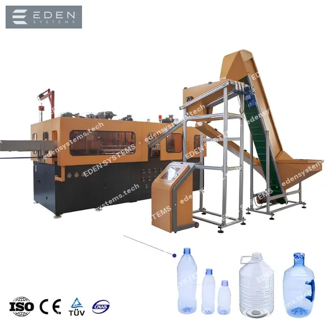
Core machines of the line
Equipment of the “Blow-Fill-Cap Combiblock” layout: each tile opens the catalog with series, specifications and a quote request for that machine.
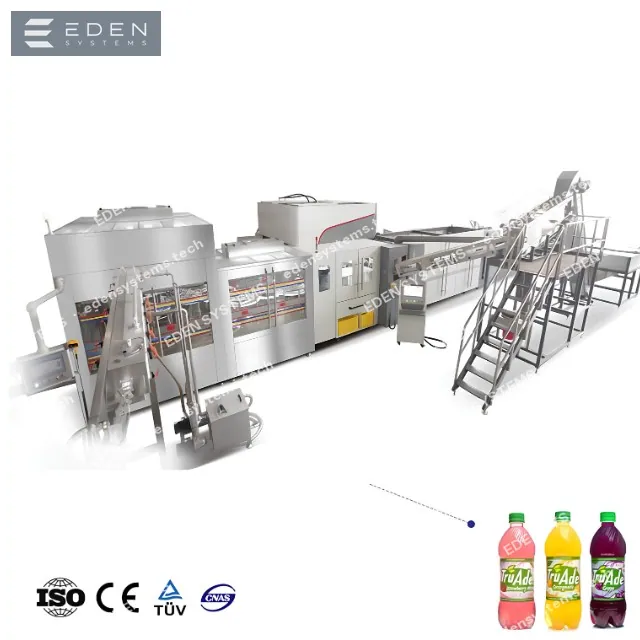
Blow-fill-cap combiblock
A preform enters the machine and a sealed, filled bottle exits: blowing, filling, and capping are combined in a single frame without an air conveyor.
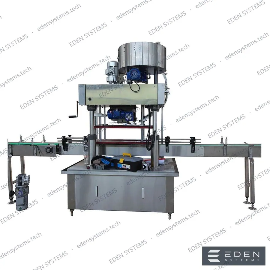
Cap feeding and rinsing
Hopper elevator, orienter, and cap rinser before each capping head, with cap-presence monitoring.
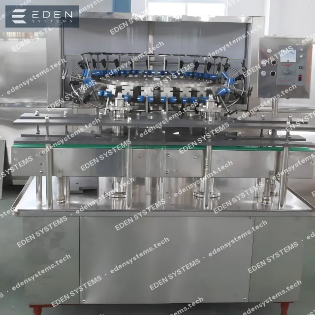
Bottle backlight inspector (FBI)
Camera inspection of the empty bottle before filling: foreign inclusions, neck deformation, and preform residue are rejected before the product is added.
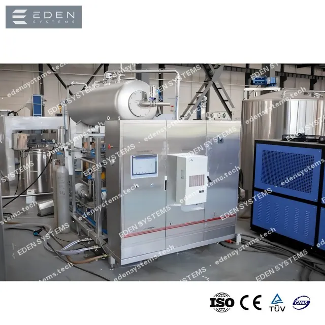
Mixer-carbonator
Water deaeration, syrup dosing, and CO₂ saturation before feeding the combiblock's isobaric valve.
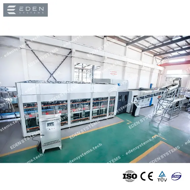
Bottle warmer
Removes condensate from the cold bottle before labeling and coding — self-adhesive labels and print adhere without peeling.
Bottle air-blow drying
Final blow-off before the labeler: remaining surface moisture is removed by an air stream.
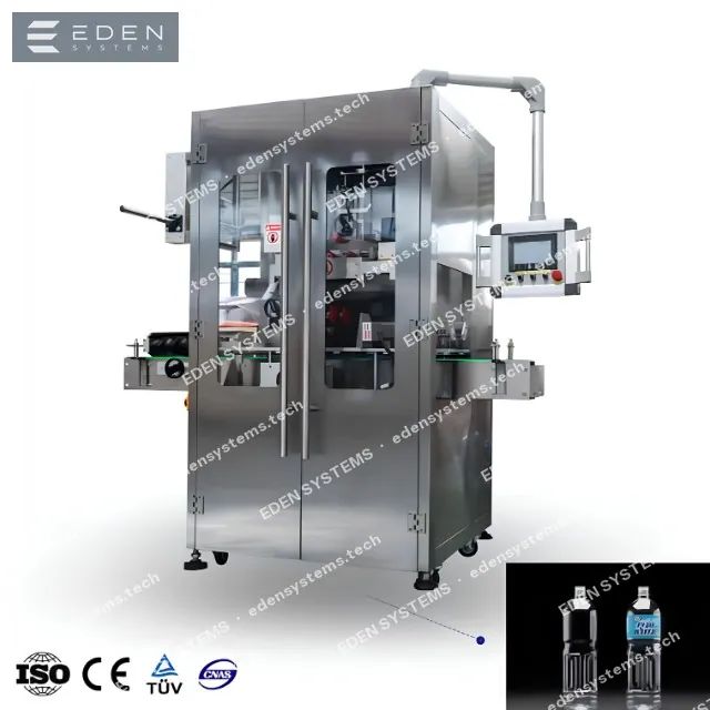
Labeling machine
PVC shrink sleeve with tunnel or glue roll-fed label — matched to the CSD packaging design.
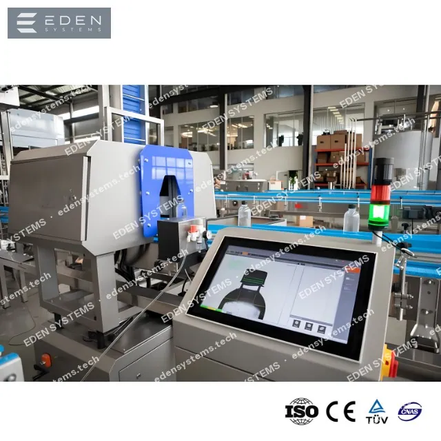
Date coder and batch marking
Continuous inkjet printing of fill date, shift, and batch number with code readability verification before packing.
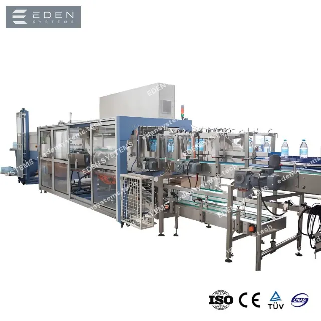
Shrink film packer
Group packing of 2×3, 3×4, or 4×6 in PE film with a shrink tunnel at the output of the high-speed combiblock.
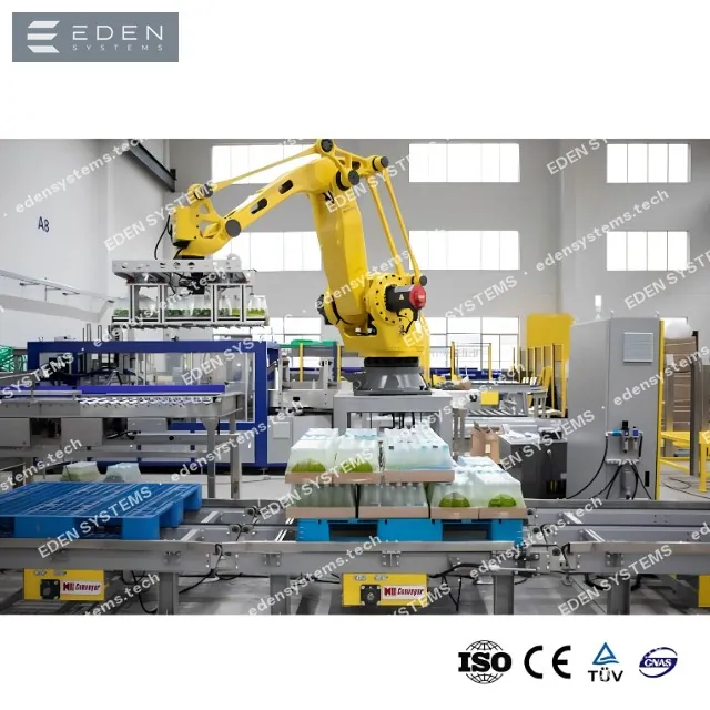
Palletizer and stretch wrapper
Layer-by-layer pallet formation at 30,000 btl/h and stretch film wrapping with pre-stretch at the line output.
Which closure do you use
The cap type defines the capping block: heads, feeding and orientation of the closure, torque or press-on force. State your option in the request and we will select the head and sorter for it.
PCO 1881 / 28 mm / 38 mm
Plastic screw cap
The tamper-evident band tears on opening. Torque is set on the HMI and monitored on every chuck.
Capping unit: Magnetic screwing head
PCO 1810 / 28 mm
Sport push-pull cap
Drinking water and isotonic drinks. The spout is fed oriented, torque 1.2–2.0 N·m, logged in the report.
Capping unit: Magnetic screwing head
Auxiliary systems of the line
The engineering utilities without which a line never reaches its rated output: water and product preparation, sanitation, container handling.
Preform feeding and orientation
The combi-block inlet.
- Hopper with an elevator and preform orienter, neck-up
- Rejection of deformed and contaminated preforms
- Accumulation buffer synchronized with oven output
- Preform-presence check at every feed position
Oven and blow-molding station
The heart of the combi-block: the container is formed right here.
- Infrared oven with zoned heating control along the preform height
- Two-stage blow with high-pressure air recovery
- Water-cooled, quick-change molds
- Direct bottle handoff to filling — no air conveyor, no dust pickup
Filling and capping block
Three operations on one frame with a single drive.
- Filling valves for gravity, isobaric or hot fill, matched to the product
- Capping heads with a magnetic clutch and torque control
- Neck-hang transfer of the container — the bottle body never touches surfaces
- Format change by recipe entry and neck-grip replacement
Compressed air and pneumatics
40-bar blow air and process air for the automation.
- Separate low-pressure process air and 40-bar blow-air circuits
- Dryer, in-line filters and receiver, dew point set for food-contact requirements
- Oil-free compressors for circuits contacting product and the container's inner surface
- Stainless steel piping with take-off points and shut-off valves at every station
CIP station (clean-in-place)
Filling-loop wash without dismantling the block.
- Alkali, acid and hot-water tanks holding temperature within ±2 °C
- Recipe-driven wash programs: phase time, concentration and flow are logged
- Flow meter on the supply line — actual flow is verified, not assumed from the nameplate
- Filtered detergent return to the tanks; discharge only once the solution is spent
Conveying systems
Discharge of the capped bottle to labeling and packing.
- Air conveyor for empty containers with air filtration and neck guide rails
- Slat-top conveyor with independent drives and accumulation buffers between stations
- AISI 304 frame, Siemens / Schneider drives and controls, Sick photo sensors
- Photoelectric jam detection with automatic section stop before a line stoppage
FAQ
When is a combiblock more cost-effective than a separate-unit layout?
From about 8,000 bph and with limited floor space. At lower speeds a separate-unit layout is more flexible: stations can be added incrementally as you grow.
Can the bottle format be changed?
Yes, by replacing the molds and adjusting the recipe. A format change takes 1.5–3 hours depending on the geometry difference.
How much does the Blow-Fill-Cap Combiblock cost?
Price on request: the budget depends on output, container type, line composition and the level of automation. After a short brief we send a preliminary estimate within 1–2 working days and a full quotation broken down by machine within 3–5 days.
What are the delivery and commissioning lead times?
Standard machines ship 8–12 weeks after the specification is confirmed, complete lines 12–20 weeks. Transport takes 2–6 weeks depending on the route; installation and commissioning on site take 2–4 weeks, with operator training included.
What output does this line reach?
The working range is 5,500–36,000 bph. Exact output is confirmed against your container, product and shift plan: we calculate the line balance and keep a margin on the bottleneck machine.
Request a quote: Blow-Fill-Cap Combiblock
Tell us the product, the container and the target output — we will return the line composition, a layout, a budget range and a delivery schedule.
Related solutions
Lines with a similar equipment set — useful when you plan several products on one site.
1,000–20,000 bph
Vegetable Oil Filling Line
Weight or volumetric oil filling into PET, glass and tinplate with capping, induction sealing, labelling and case packing.
Open solution2,000–36,000 bph
Drinking Water Filling Line, 0.33–1 L
Rinser-filler-capper monobloc for PET, water treatment, labelling and shrink packing.
Open solution600–3,600 bph
Water Filling Line, 3–10 L
Filling of large-format handled PET containers, capping and shrink packing.
Open solutionServices for this line
Engineering, logistics, installation and service that turn this line into a working production site.
Digital layer
Any line can be supplied with a digital layer
SCADA, MES, OEE monitoring, batch traceability and integration with plant systems — engineered together with the line, not bolted on later.